|
Shenzhen Sinofine Machinery Co.,Ltd.
|
Chemical Process Pump Chemical Transfer Pump
| Place of Origin: | Zhejiang, China (Mainland) |
|
|
|
| Add to My Favorites | |
| HiSupplier Escrow |
Product Detail
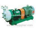
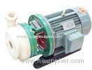
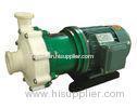
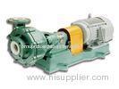
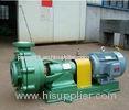
Fluorine Plastic Alloy Horizontal Centrifugal Pump For Chemical Industry</spa
Fluorine Plastic Alloy Horizontal Centrifugal Pump For Chemical Industry
Model Significance:
80FSB-50
80 - The pump’s inlet diameter is 80mm
FS - The material of the liquid carrying part is fluoroplastic alloy
B- Single-stage single-suction centrifugal pump
50 - The pump lift is 50mm
Sinofine FSB fluorine plastic alloy pump is made up of pump casting, impeller, rear cover, seal,brace, shaft, bearing, coupling, tight bolt, nut and baseplate. For pump casting,there is a separately flange ring which is made of modeled plastic alloys installed in the link part of two sides.The modeled plastic alloys installed in the right side of rear covermodeled plastic alloys installed in the right side of rear cover.Impeller is designed for link shaft method.The metal shaft, which is made of high quality steel alloy and there is plastic alloy modeled on the exterior, fixs the impeller and metal shaft into integration and ensure the torque followed the rotating between bottom shaft and impeller. Thus, the wet medium part is plastic alloy.It is high mechanism seal.Take the WB2-type, ST-type which is the adjustable face mechanism seal technology without using the cooling water. Be made of silicon carbide, high purity alumina ceramic, filled PTFE, graphite and other materials.
Sinofine FSB centrifugal pump take the liquid-carrying parts of the FSB and FSB-D series centrifugal pump which they are all made of fluoroplastic alloy. Their structures are compact, operations easy, and prices inexpensive. The pump casings, impellers, and mechanical seals, etc. of the models are interchangeable, and the models are warmly accepted among industries such as pesticide, electronics, and papermaking..Sinofine FSB centrifugal pump works by the conversion of the rotational kinetic energy, typically from an electric motor or turbine, to an increased static fluid pressure. The rotation of the pump impeller imparts kinetic energy to the fluid as it is drawn in from the impeller center and is forced outward through the impeller vanes to the periphery. As the fluid exits the impeller, the fluid kinetic energy is then converted to pressure due to the change in area the fluid experiences in the volute section. Typically the volute shape of the pump casing , or the diffuser vanes (which serve to slow the fluid, converting to kinetic energy in to flow work) are responsible for the energy conversion. The energy conversion results in an increased pressure on the downstream side of the pump, causing flow.
Our products all adopt the computer design and optimization of processing, the company has strong technical force, rich production experience and perfect detection means, so as to ensure the product quality is stable and reliable.
|
Model |
Flow |
Lift |
Efficiency |
NPSh |
Inlet×Outlet |
Speed |
Motor Power |
Weight |
|
m3/h |
m |
% |
m |
mm |
r/min |
kw |
kg |
|
|
25FSB-25 |
2 |
25 |
22 |
3.0 |
25x25 |
2900 |
1.5 |
48 |
|
* 36 |
25 |
30 |
||||||
|
6 |
|


